VIPER 6.0™ Code
VIPER (Viscous Interaction Performance Evaluation Routine) was originally developed to help assess boundary layer interactions for high area ratio nozzles. Since the release of Version 3.6, there have been many improvements and corrections made to the that version.
Given below is a brief summary of upgrades and enhancements contained in Version 6.0
New in VIPER 6.0™
Features of VIPER 6.0™
A new Subsonic Transonic Navier-Stokes Solver
- Includes full mixing of striations in LRE’s.
- Includes two phase flow with finite rate chemistry, a new breakup model, and phase change.
Two-Phase flow
New GUI based on Python for Windows and Linux
The two-phase transonic module TRAN2P was incorporated into the VIPER code
A slip wall boundary condition
STS (Full Two_phase Flow Navier-Stokes Solver) option for the transonic with film cooling and added option for two slot injection ports
New Breakup and Agglomeration models based on the TAB (Taylor Analogy Breakup) Model
Increased maximum number of species (from 40) to a user input value
Option to use either JANNAF Thermodynamic file (5-coefficient fit for specific heat) or CEA Thermodynamic database (7-coefficient fit for specific heat)
MPI version for STS to reduce the run time if the STS module is extended to the exit plane (Available on Linux platform only)
Added capability for domain decomposition for extending STS to the exit plane (more efficient for Linux-MPI)
Added phase change capability to STS module (Especially needed for extended STS solution to the exit plane)
Damping control at the symmetry centerline allows for a wider range of problems to be solved
A source flow option is available
Standard LINPAC matrix routines are incorporated into the basic matrix solvers so that users can take advantage of machine optimized versions of these routines.
In order to view the results of the calculations effectively VIPER 6.0™ writes output files for TecPlot™ and ParaView graphics packages
An interface which transfers nozzle exit plane flow properties from VIPER to SPF-3, the Standard Plume Flowfield computer program is available
The PNS wall boundary conditions allow a steady state temperature be calculated for a radiation cooled nozzle
Film Cooling in the PNS module
Post-processing with Tecplot program
option to combine STS and PNS solutions for both phases into a single Tecplot formatted file
Auxiliary calculations and output have been added so that total flow properties for a Pitot tube probe are available. The method assumes frozen flow through a normal shock, followed by stagnation
Near plume flowfield option to allows the computation to proceed past the nozzle exitplane for one or two nozzle exit radii
Available on Windows and Linux platforms.

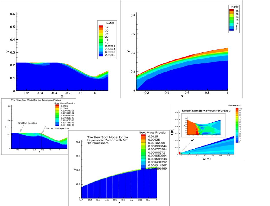
Soot Model - Transonic/Supersonic(Top Left)- Droplet Breakup and Phase Change (Upper Right), MPI for Soot Model
